Vision-Guided Autonomous Drone
[One or two sentences: what the drone does, and the thing about it worth knowing.]
- Year
- 2026 – present
- Status
- Verified in simulation; in development on the vehicle
- Context
- Personal project
- Role
- Airframe, mechanical design, perception, control, test infrastructure
- Stack
- Python 3 · ArduPilot 4.6 · OpenCV · MAVLink 2 · picamera2 · SolidWorks
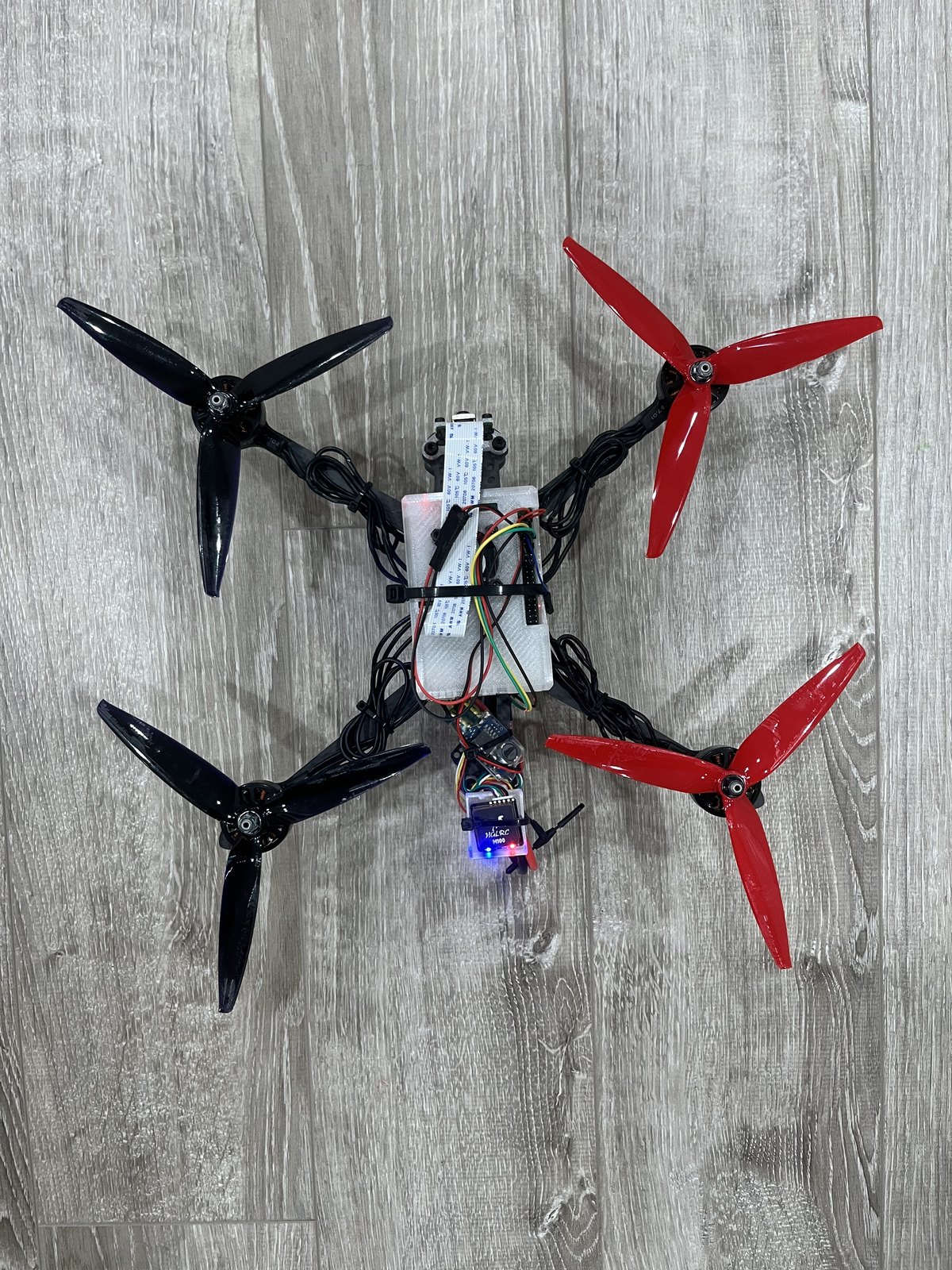
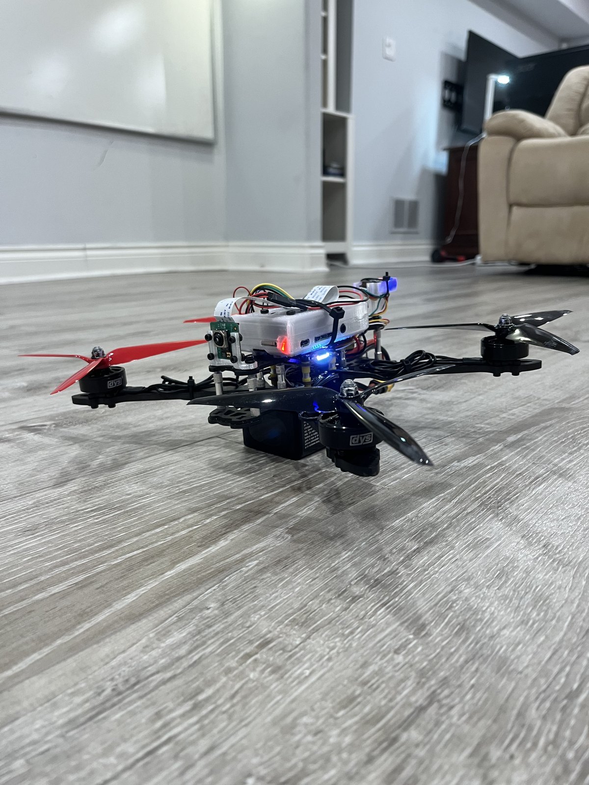
[Caption both photographs — what the reader is looking at.]
What it does
[What the drone does, in plain terms. Tag detection, what it holds position relative to, and what the pilot still controls.]
How the control loop works
[The loop, step by step — from a camera frame to a command the flight controller acts on.]
pitch = K_p · e_forward + K_d · v_forward
[Why the derivative term is not optional — and what happened in simulation without it.]
[What the controller does when it loses the tag, and why it does that rather than searching.]
What I built
- [The vehicle — airframe, components, wiring, configuration.]
- [The custom mechanical parts, and what they had to hold.]
- [The perception pipeline.]
- [The outer control loop.]
- [The ArduPilot integration.]
- [The test infrastructure, and what it caught.]
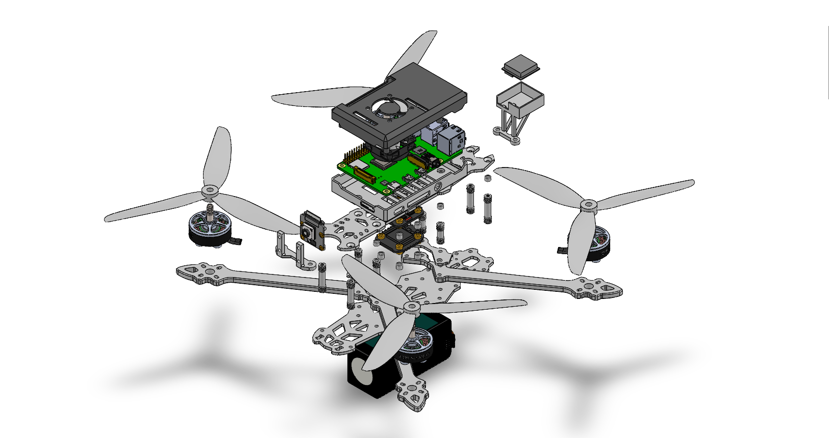
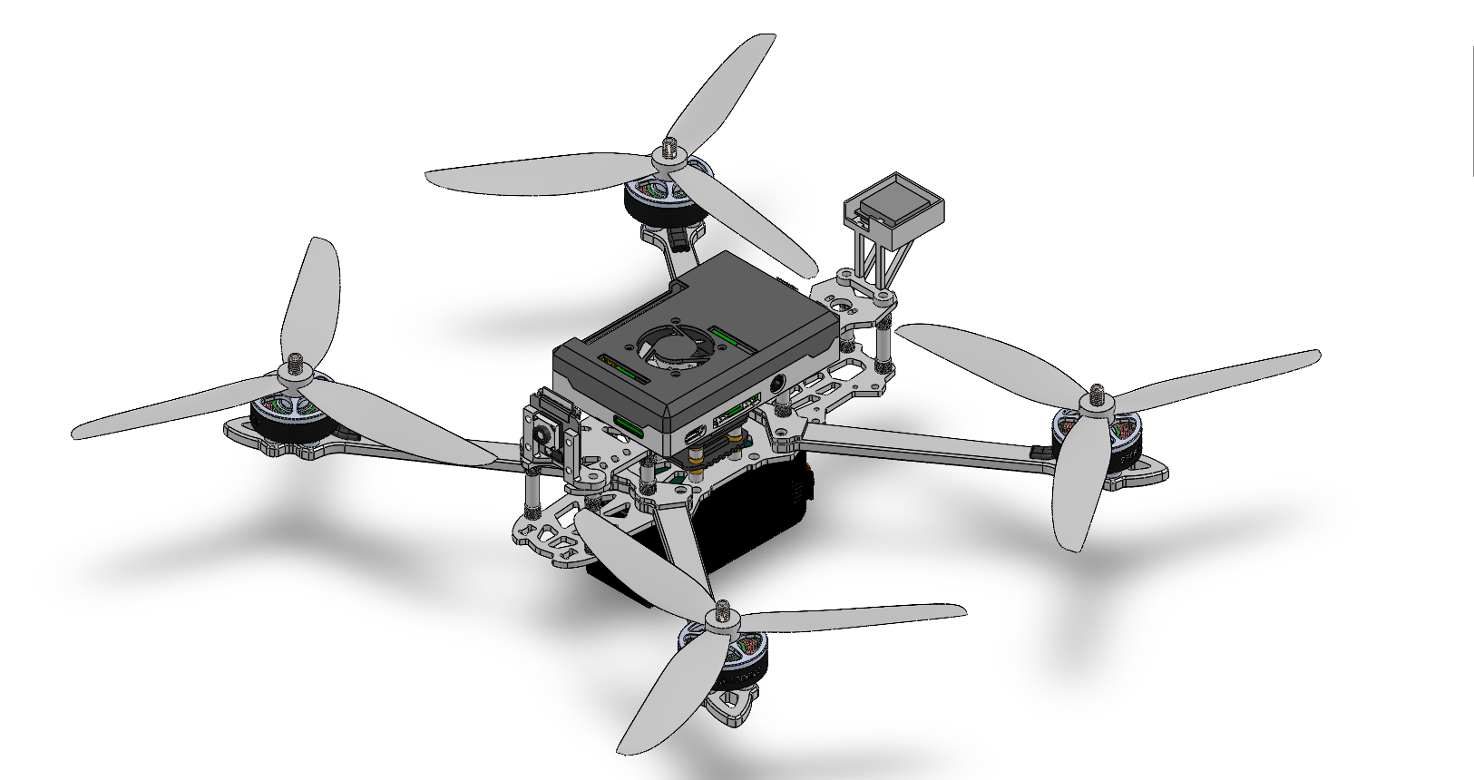
The airframe, in CAD
[Why these mounts had to be modelled against measured dimensions rather than eyeballed.]
Technical overview
| Airframe | Custom 7-inch quadcopter, ~816 g, 6S |
|---|---|
| Flight controller | SpeedyBee F405 V3 running ArduCopter 4.6 |
| Companion computer | Raspberry Pi 4 |
| Camera | Camera Module 3 (IMX708), 1280×720, 2 ms shutter, focus fixed at 1 m |
| Perception | AprilTag 36h11 via OpenCV ArUco; monocular pose from tag corners |
| Control | Outer PD loop on relative position; yaw held on the tag bearing |
| Communication | UART, MAVLink 2 at 921600 baud |
| Flight mode | GUIDED_NOGPS, from a custom ArduPilot build |
| Simulation | ArduPilot SITL, with a synthetic tag closing the full loop |
| Mechanical | SolidWorks — custom Raspberry Pi, camera and GPS mounts |
| Radio / GPS | ELRS; HGLRC M100 Pro GPS with QMC5883L compass |
Status
| Component | Status |
|---|---|
| AprilTag detection and pose estimation | Running on the vehicle |
| Camera tuning for vibration and blur | Measured on hardware |
| MAVLink link and telemetry | Hardware tested |
| Outer PD controller | Tuned in SITL |
| Control path and sign conventions | Verified in SITL |
| Closed-loop convergence to a tag | Verified in SITL |
| Camera intrinsic calibration tooling | Implemented |
| Autonomous position hold in physical flight | In development |
| Inner-loop AUTOTUNE on the real airframe | Not yet performed |
[What works in simulation, what works on the vehicle, and the gap between them.]
Limitations and what comes next
[The limiting factor, and why more software will not fix it.]
- [Next step.]
- [Next step.]
- [Longer term.]