Rocker-Bogie Swerve-Drive Chassis
[One or two sentences: what the chassis was for, and what the suspension and swerve drive do.]
- Year
- Jun – Aug 2024
- Status
- Built and tested
- Context
- Mechanical design internship, Dr Robot Inc.
- Role
- Mechanical design, simulation, wiring and integration
- Stack
- SolidWorks · Unity · NVIDIA Jetson Nano
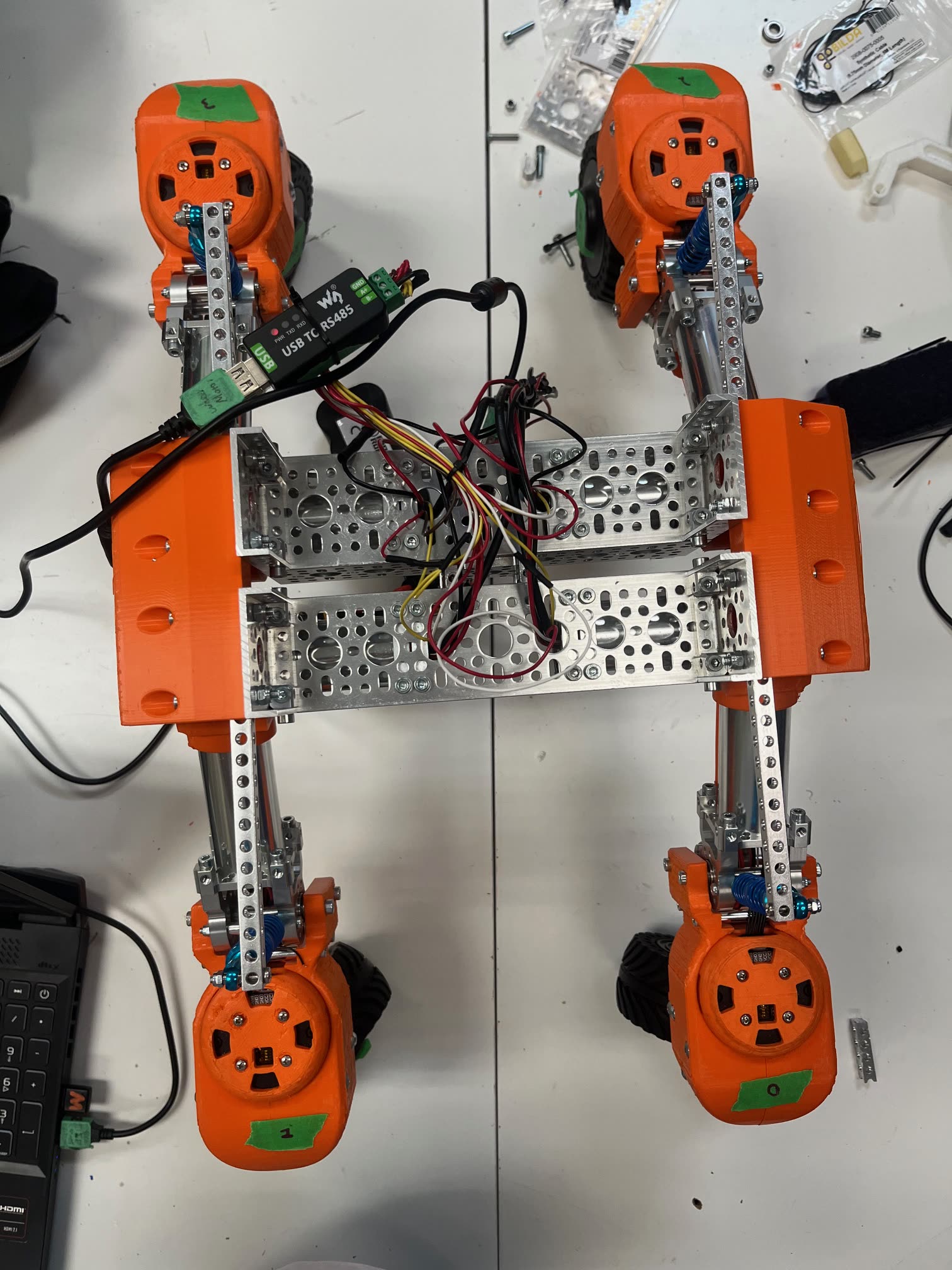
What it does
[What the suspension and the swerve drive each do, and why they go together.]
[What it was for, and what it had to handle.]
The swerve module
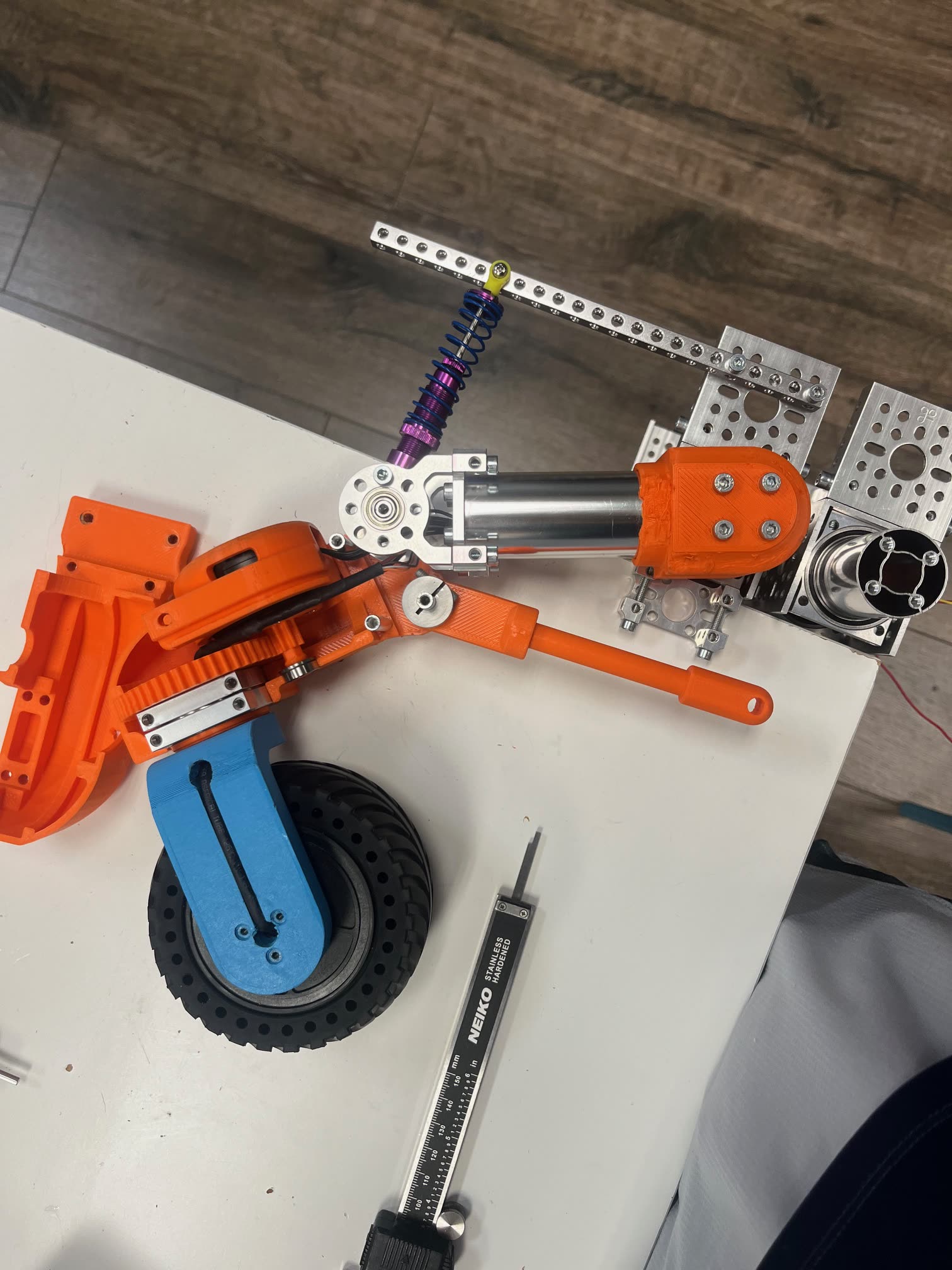
[What made the module hard to package, and how you resolved it.]
Simulate first, then build
[What you exercised in Unity before anything was machined.]
[What simulation caught before it cost you a part.]
What I built
- [The suspension design.]
- [The Unity simulation.]
- [The physical prototype.]
- [The electronics integration.]
Technical overview
| Suspension | Rocker-bogie with coilover spring elements |
|---|---|
| Drive | Swerve — independently steered wheels |
| Simulation | Unity, with swerve-drive odometry |
| Compute | NVIDIA Jetson Nano |
| Sensing | Camera, for navigation and computer vision |
| CAD | SolidWorks |
Limitations and what comes next
- [Terrain or loads it could not handle.]
- [A gap between simulation and the real thing.]
- [What the next revision would change.]